Applications
Reusable dynamics in engineering simulation.
A disturbance on a network. A signal through a circuit. A controller waiting for its next sample. TDSE brings reusable subsystem responses to the simulations behind them.
01 / Application
Power-system & EMT simulation
Follow the disturbance. Reuse the network response.
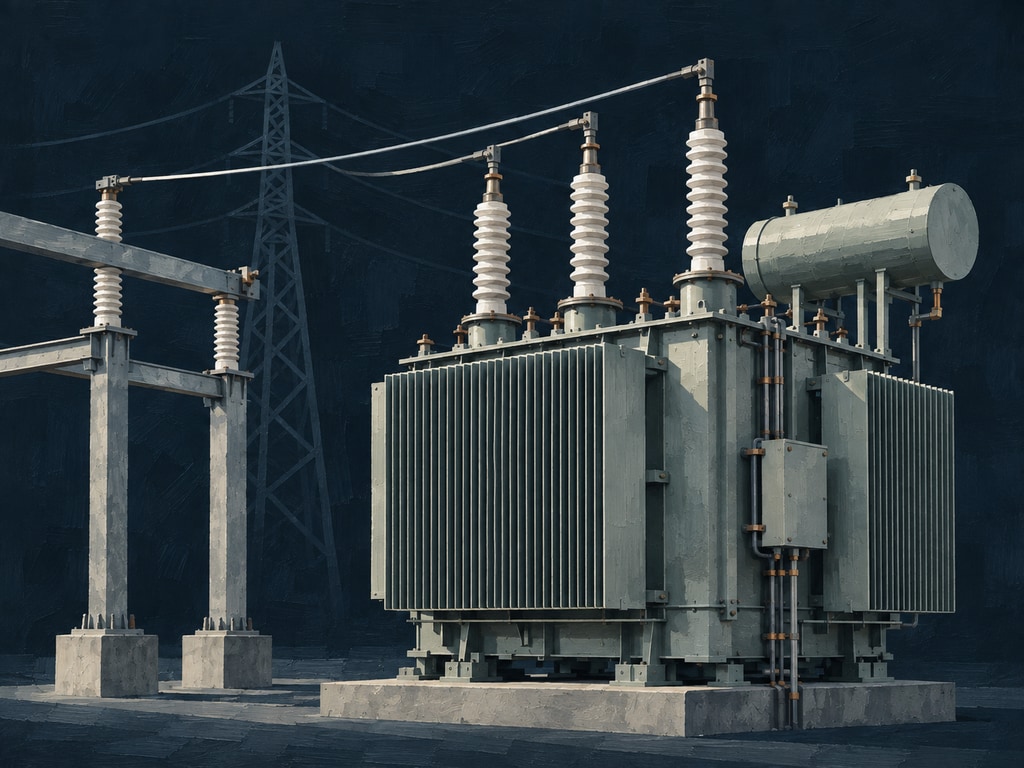
The event changes. Much of the network does not.
A fault, a breaker operation or a converter transient sends a disturbance through lines, cables and the surrounding network. The waveforms change at every step; the dynamics of a fixed linear region remain the same.
TDSE prepares that region once and reuses its response at every timestep. Frequency-dependent line and cable models can enter through their frequency responses, while your simulator advances the devices and events around the equivalent.
Less work inside the unchanged region leaves more room for the study itself. Keep that region fixed, and the prepared model can also serve the next fault location, switching sequence or controller test outside it.
Model scope and supporting evidence
- Start with
- A supported circuit / RAW model or independently prepared response data, with explicit ports, operating assumptions and input-hold conventions.
- Integration boundary
- The prepared region must remain linear with unchanged dynamics. The host retains nonlinear devices, switching, timestep policy and coupling. Events that change the region itself require an updated model; the partition must be validated.
- Available evidence
- Public IEEE118 frequency, timestep, two-port and short-fault studies; cross-system timestep sweeps on ACTIVSg200 and NREL240.
- Validate in your environment
- Your partition and event family, reference windows, initialization, coupling stability, and end-to-end execution cost.
02 / Application
Circuit, signal & power integrity
Carry circuit behavior from frequency response into time.
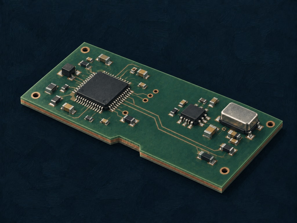
Follow the signal. See the supply respond.
A package, connector or cable shapes the signal that passes through it. A power-delivery network shapes the voltage seen by a changing load. Their frequency responses reveal the resonances, losses and delays behind the transient waveform.
TDSE Circuit compiles supported circuit models, runs frequency and transient analyses, and exposes probe results. It also prepares linear regions for TDSE Runtime, bringing characterized circuit behavior into a host simulation.
Once prepared, the region responds at each timestep without repeating its internal network solve. Change the excitation or surrounding circuit while retaining the same region, and its prepared response remains reusable.
Model scope and supporting evidence
- Start with
- Supported circuit inputs or response data with declared units, port ordering, frequency grid and reference conventions.
- Integration boundary
- A reusable circuit or interconnect region. TDSE Circuit adds analysis and model preparation; Runtime executes the qualified representation inside your host.
- Available evidence
- The Circuit manual documents supported elements, import paths, native APIs, frequency and transient analysis, and model-preparation workflows. Integration with a particular host requires an adapter and validation in that environment.
- Validate in your environment
- Model coverage, response bandwidth, passivity / stability requirements, preparation cost, repeated-run benefit and transient reference accuracy.
03 / Application
Real-time & hardware-in-the-loop
Move preparation out of the loop. Leave room for the next step.
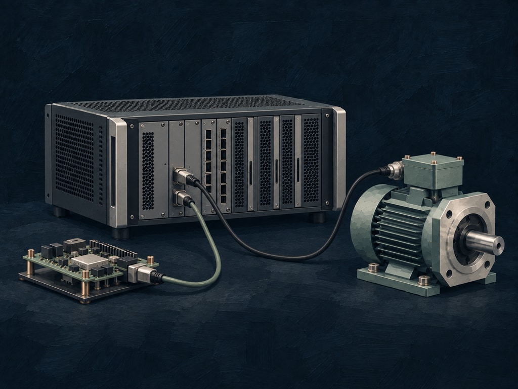
Do the preparation before the clock starts.
In a controller test or hardware-in-the-loop system, simulation shares every timestep with I/O, synchronization and control logic. The deadline belongs to the whole loop, not just the mathematical model.
Prepare the subsystem model offline, then allocate and prepare its runtime resources before entering the timed loop. During execution, TDSE evaluates the prepared response as the host exchanges signals and advances the test.
The repeated subsystem calculation becomes a smaller part of the online workload. That creates room to evaluate a finer timestep or a larger surrounding model against the actual target's execution budget.
Model scope and supporting evidence
- Start with
- A qualified Runtime pack, a fixed target platform and the intended host scheduling, I/O and synchronization configuration.
- Integration boundary
- The host owns scheduling and the real-time deadline. CPU is included in Runtime; GPU and FPGA execution have separate provider and target qualification.
- Available evidence
- Prepared-step runtime measurements across CPU, GPU and FPGA, with configuration and correctness evidence retained.
- Validate in your environment
- Worst-case and tail timing, jitter, memory, transfers, I/O, fault handling and deadline behavior under the actual host workload. A median kernel result is not a real-time guarantee.
Future directions
More worlds of dynamics.
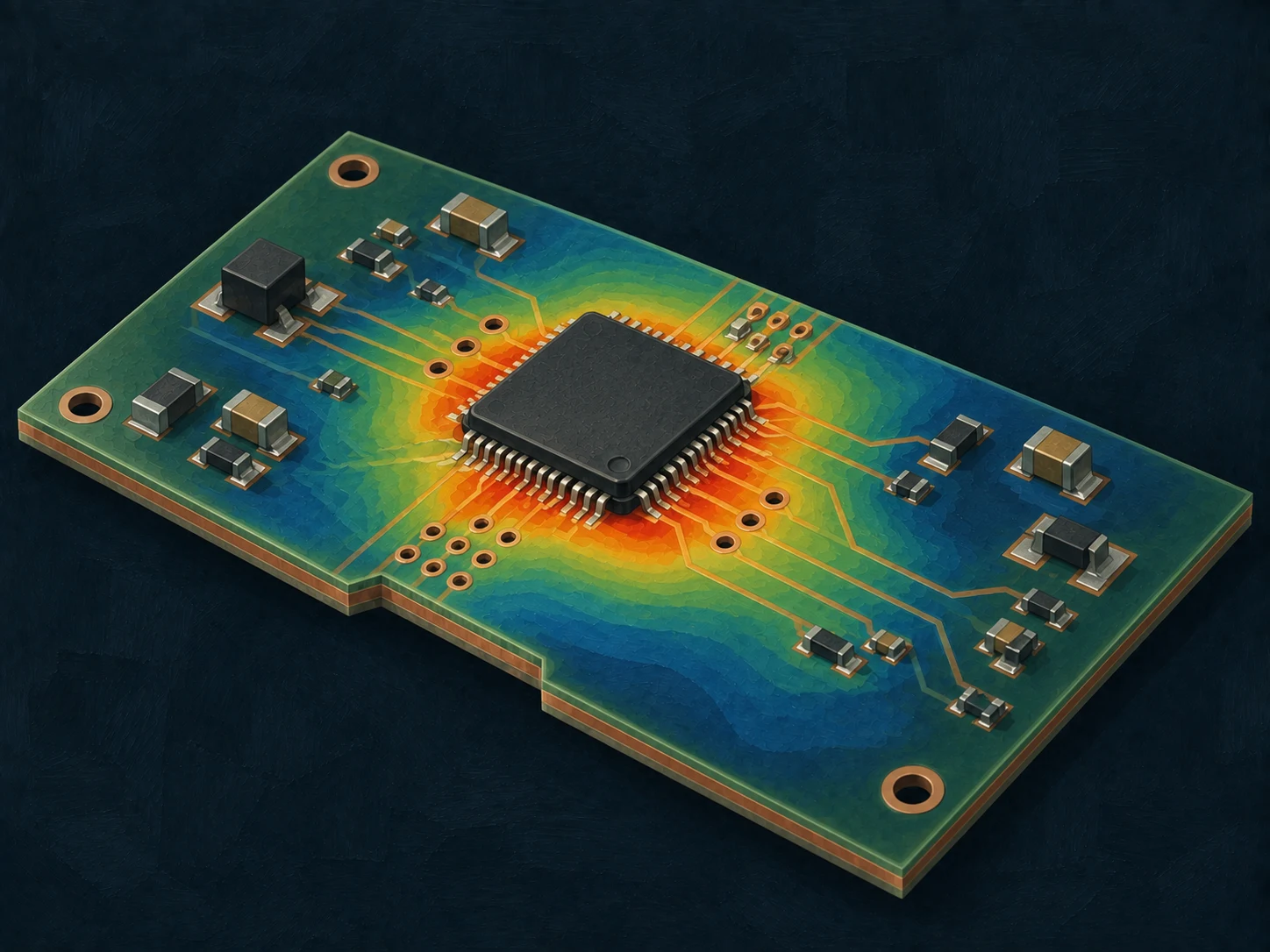
Thermal simulation
From power dissipation to thermal response.
A changing load heats a chip, board or enclosure. A reusable linear thermal model could carry that history into temperature predictions without repeating the full spatial calculation at every step.
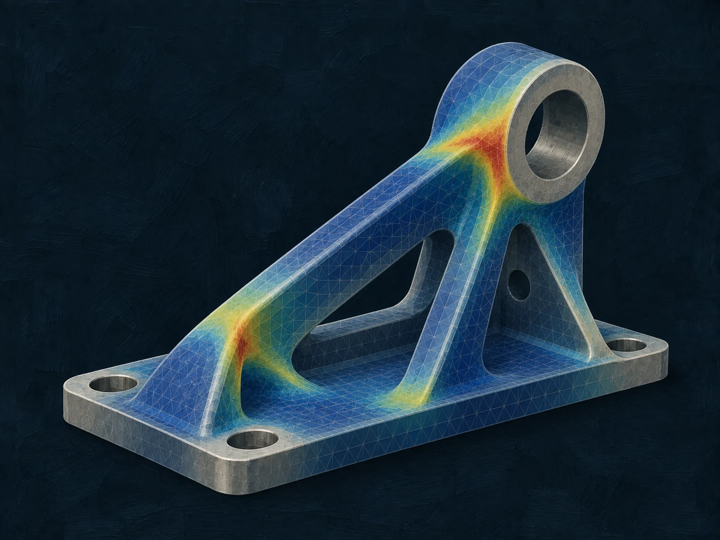
Structural dynamics
From applied loads to mechanical response.
A force excites a bracket, frame or assembly. A prepared linear structural response could bring its vibration and displacement into repeated load studies or a larger system simulation.
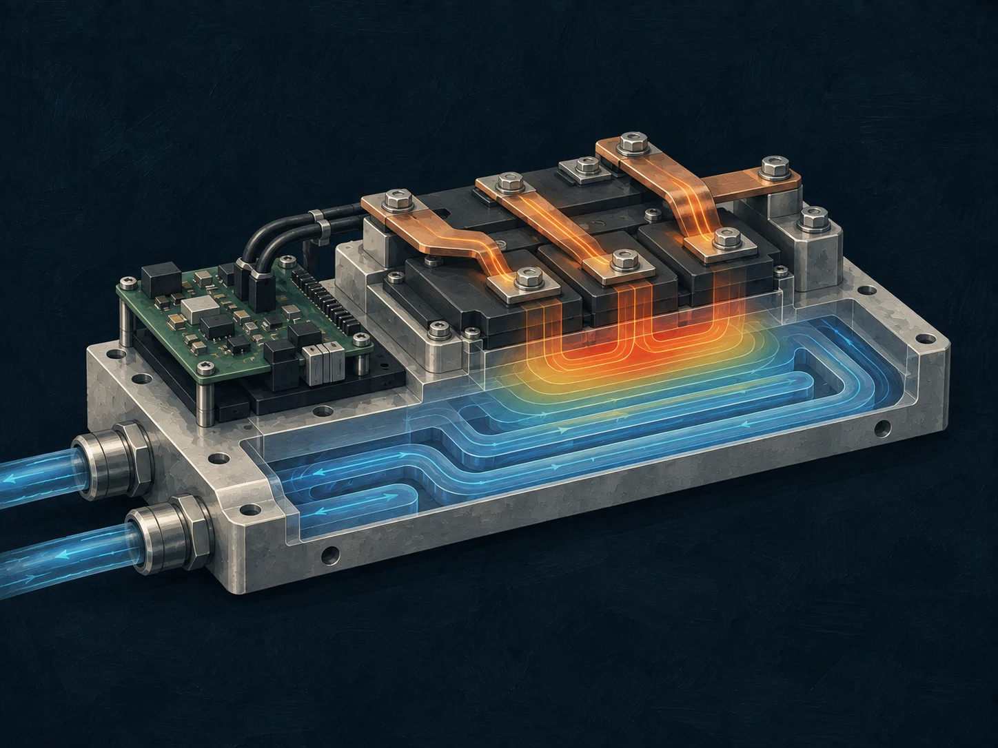
Multiphysics coupling
Where electrical, thermal and fluid systems meet.
Power losses heat a module; a cooling circuit carries that heat away. Reusable linear regions could exchange responses through defined interfaces, leaving the changing interactions to the coupled simulation.
Future application directions, not currently released domain products. The illustrations are conceptual, not simulation results.